

EtherCAT devices and mapping
An EtherCAT connection needs the list of the devices (slaves) on the bus, in bus order, with their process data (PDO entries). Then you map PDO entries to PLC variables.
Ways to add the devices
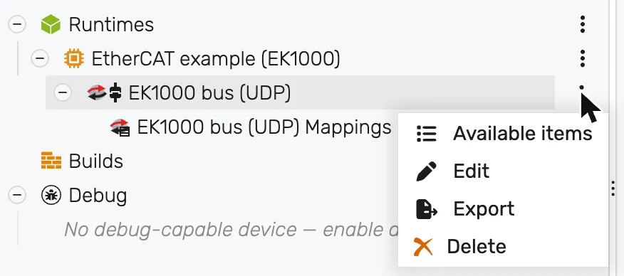
Section titled “Ways to add the devices”Open the menu (⋮) of the connection and select Available items. The same dialog opens from the list icon in the toolbar of the Mappings tab. It shows the devices of the connection and has four actions:
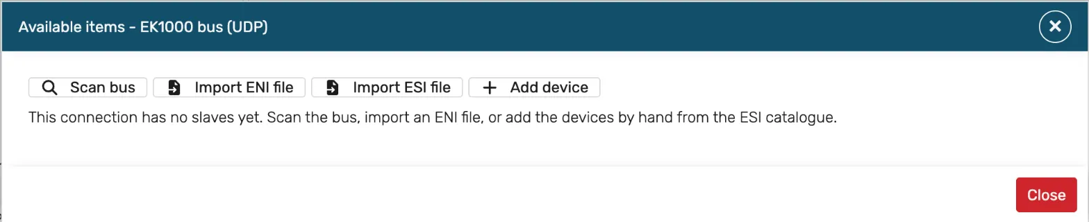
| Action | When to use it | Result |
|---|---|---|
| Import ENI file | You have a TwinCAT project of the bus (recommended) | All devices with the PDO assignment and start-up commands of TwinCAT |
| Scan bus | The bus is connected and you imported the ESI files of the devices | The devices found on the bus, matched with the ESI catalogue |
| Add device | No bus at hand, or you want to compose the bus by hand | One device from the ESI catalogue at a position |
| Import ESI file | Before a bus scan or Add device | Device types in the ESI catalogue of your organization |
Import ENI file, Scan bus and Add device replace devices of the connection. A mapping is removed when its device or its PDO entry no longer exists. The result lists every removed mapping.
Importing an ENI file
Section titled “Importing an ENI file”The ENI file (EtherCAT Network Information) describes the bus as TwinCAT configured it.
-
In TwinCAT, select the EtherCAT master of the EK1000, open the EtherCAT tab and select Export Configuration File…. Save the XML file.
-
In logiccloud, open Available items of the connection and select Import ENI file. Select the file and select Import.
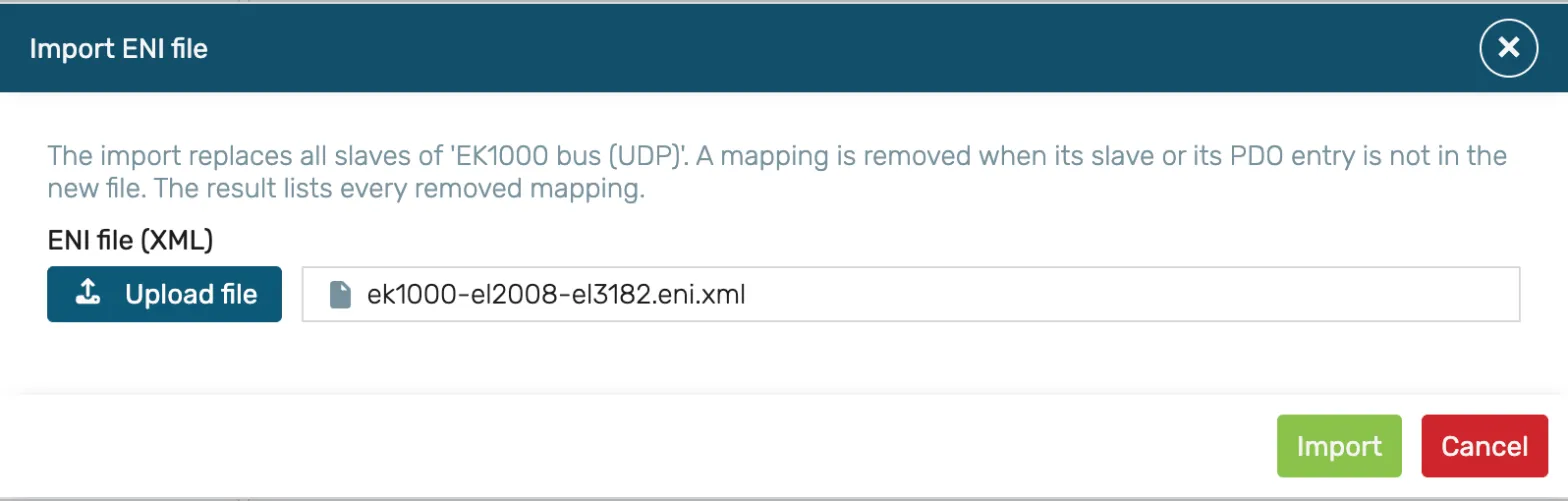
Expected result: Slaves imported: N, and a list of removed mappings if there were any.
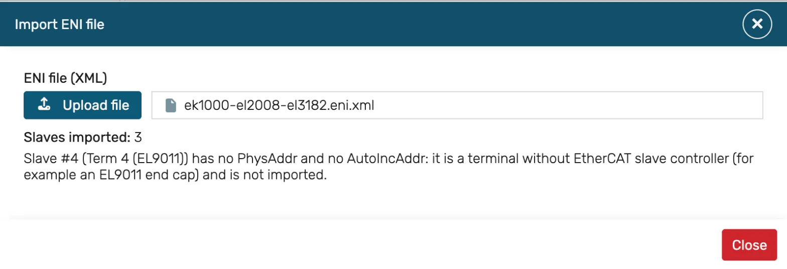
Available items now lists every device with its position, identity and PDO entries:
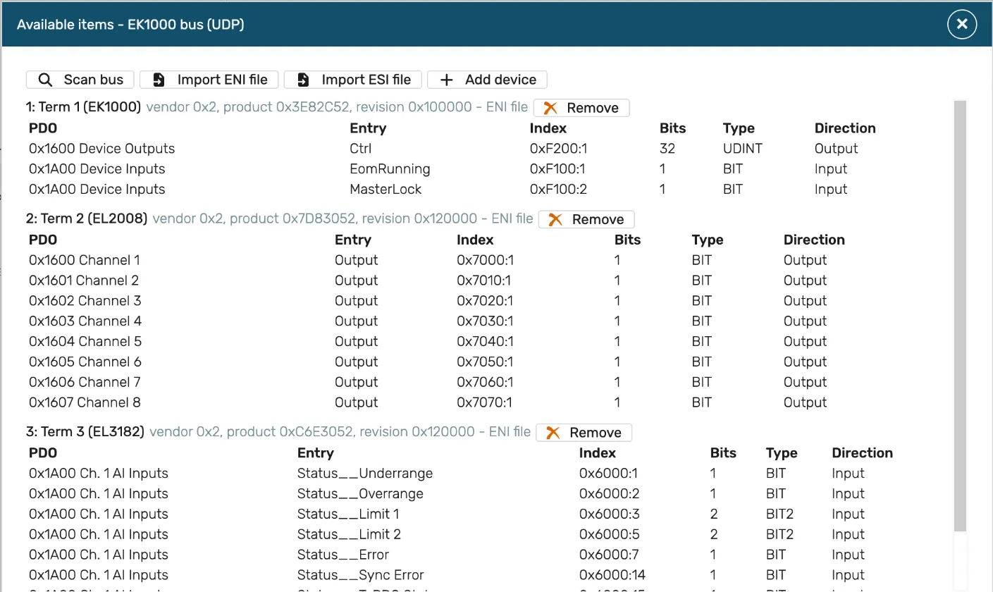
- The connector uses the slave identities, the PDO assignment and the start-up commands (InitCmds, including CoE SDO downloads) of the file. Start-up commands for registers that the master sets itself are not replayed (log line
Init command not replayed: the master owns these registers). - Terminals without an EtherCAT slave controller, for example the EL9011 end cap, are not imported. The import shows a warning for each.
- The file can be up to 20 MB.
- The order of the terminals in the file must be the order on the bus. When the terminals are wired in another order than in the TwinCAT project, the connector stays in PREOP and logs
Topology mismatch. Correct the wiring, or export the file again from a TwinCAT project that matches the wiring.
Importing ESI files
Section titled “Importing ESI files”An ESI file (EtherCAT Slave Information) describes the device types of one vendor. Use the original files of the vendor, for example Beckhoff EL2xxx.xml from the TwinCAT folder Config\Io\EtherCAT or from the vendor’s website.
- Open Available items of the connection and select Import ESI file. You can also use Import ESI file on the EtherCAT node.
- Select the file and import it.
Expected result: Created: n, Updated: n, Skipped: n. The device types are available for all EtherCAT connections of your organization.
Scanning the bus
Section titled “Scanning the bus”The scan runs on the device: the runtime with this connection must be installed on a device, and no other master may run the segment.
- Open Available items of the connection and select Scan bus. The scan starts at once and takes up to 45 seconds.
- Check the result table: position, name, vendor ID, product code, revision, and Matched or Not matched in the ESI column.
A device with Not matched has no device type in the ESI catalogue and cannot be mapped. Import the ESI file of its vendor and scan again, or import an ENI file.
Adding a device by hand
Section titled “Adding a device by hand”- Open Available items of the connection and select Add device.
- Search the device type, for example
EL1008, and select it. - Enter Position on the bus (1 is the first device after the master). A device at this position is replaced.
- Select Add.
At start-up the connector checks that the device at each position has the configured vendor ID, product code and revision. Additional devices at the end of the bus are allowed.
Mapping PDO entries to PLC variables
Section titled “Mapping PDO entries to PLC variables”-
Declare the PLC variables in the program: read-only variables (for example
{ IN }) for inputs, writable variables (for example{ OUT }) for outputs. Save the program, then open Configurations > your configuration (for examplemy_config) > Inputs/Outputs and select Refresh: only variables in this list can be mapped. -
Open the node <connection name> Mappings under the connection.
-
Add a row per value: with the add icon (Add mapping) one row at a time, or with Advanced fill, which adds one row per selected variable. In each row, select the PLC variable and the EtherCAT item (a PDO entry of a device). Type part of the label, for example
0x7000:1orMasterLock, to filter the list. The Direction follows from the entry. The Type is preset from the device description.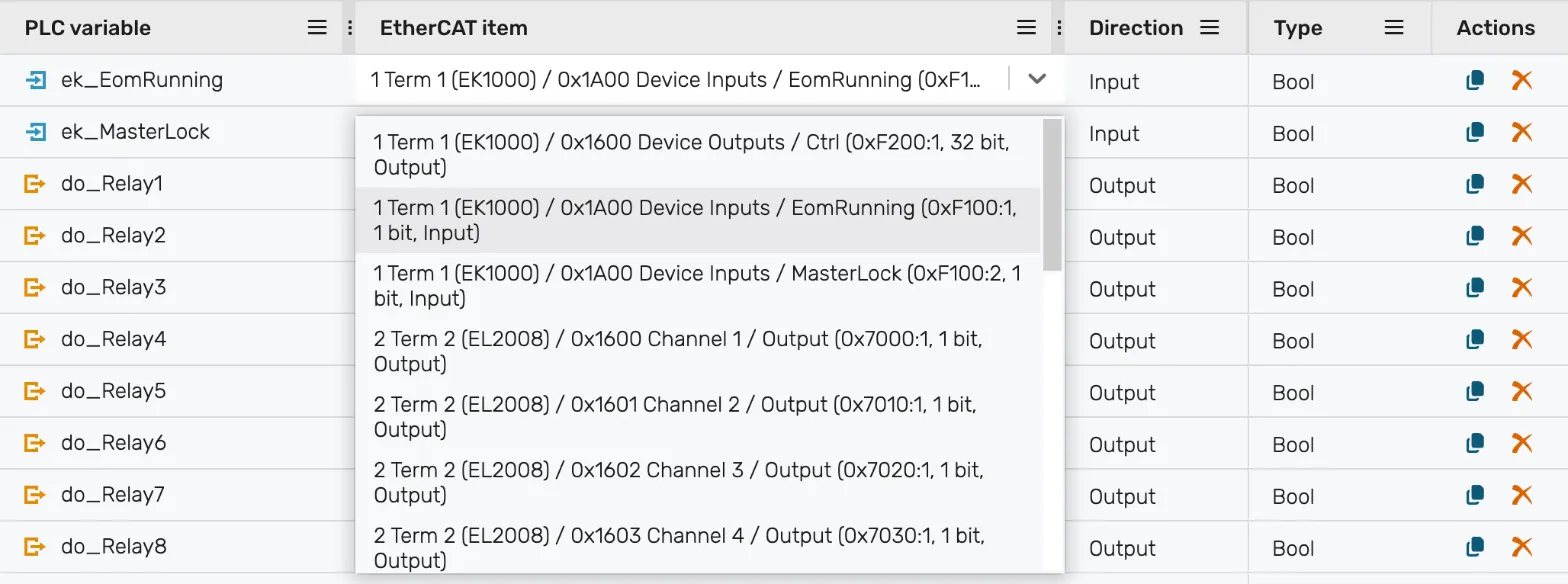
-
Save with the save icon (Save all) in the toolbar. One save replaces all mappings of the connection.
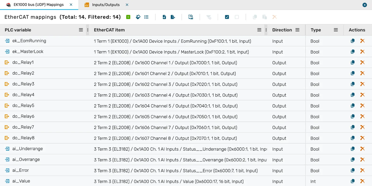
Import mappings reads a CSV file with the columns of the grid: PLC variable, EtherCAT item and Type. Use Export mappings to get a file in this format. The EtherCAT item is the key <position>:<PDO index>:<entry index>:<sub-index> in decimal, for example 2:5632:28672:1 for 0x1600 / 0x7000:1 of the device at position 2. The type is read without regard to case (BOOL or Bool). A row whose item is not on this connection is marked, and the save is blocked with The PDO entry ... is not on this connection: select the item again.
| Direction | Data flow | PLC variable |
|---|---|---|
| Input | device to PLC (TxPDO) | read-only |
| Output | PLC to device (RxPDO) | writable |
The data type must be as wide as the PDO entry:
| Entry width | Data types |
|---|---|
| 1 bit | BOOL |
| 8 bits | BYTE, SINT, USINT |
| 16 bits | WORD, INT, UINT |
| 32 bits | DWORD, DINT, UDINT, REAL |
| 64 bits | LWORD, LINT, ULINT, LREAL |
A row with an invalid value blocks the save. The message names the row, for example The type INT does not fit a PDO entry of 32 bit(s).
Deploying and checking
Section titled “Deploying and checking”- Build the project and deploy the runtime to the device.
- Open the log of the EtherCAT connector on the device.
Expected log lines within about 10 s:
EtherCAT scan finishedwith the number of slaves.EtherCAT master statewithstate=OPand the number of slaves.
Then check the values in the debug view or the HMI: inputs change with the process, and outputs written by the PLC appear on the terminals (for example the LEDs of an EL2008).
If the connector stays in PREOP or reconnects, see Troubleshooting.
Export and import
Section titled “Export and import”Select the connection, then Export, to save it as a file. Use Import EtherCAT connection on the EtherCAT node to add it to another runtime.