

Example: EK1000 with EL2008 and EL3182
This example builds a complete project: logiccloud switches the 8 outputs of an EL2008 and reads channel 1 of an EL3182 through an EK1000 over UDP. The setup is the one of the logiccloud test with a Beckhoff EK1000 on a Raspberry Pi 4 class device (arm64).
The setup
Section titled “The setup”| Part | Value in this example |
|---|---|
| logiccloud device | Raspberry Pi 4, linux/arm64, logiccloud Control 6.92.8 or later, IP address 192.168.3.102 |
| Router | 192.168.3.1, routes between 192.168.3.0/24 and 192.168.2.0/24 |
| EK1000 | IP address 192.168.2.110, EtherCAT Open Mode set to UDP |
| Bus, in wiring order | EK1000, EL2008 (8 digital outputs), EL3182 (2 analog inputs), EL9011 (end cap) |
| ENI file | exported from the TwinCAT project of this bus |
Replace the IP addresses with yours.
1. Prepare the EK1000 and the network
Section titled “1. Prepare the EK1000 and the network”Follow Setting up the EK1000:
- Set Open Mode to UDP in TwinCAT and export the ENI file (Export Configuration File…).
- Shut down the TwinCAT PC or disconnect it from the network, then switch the power of the EK1000 off and on.
- On the logiccloud device, check the route:
ip route get 192.168.2.110showsvia 192.168.3.1, andping -c 3 192.168.2.110gets 3 replies.
2. Create the project and the PLC program
Section titled “2. Create the project and the PLC program”- Create a project for the platform linux/arm64.
- Replace the program
my_programwith this program. The variables marked{ IN }receive the bus inputs, the variables marked{ OUT }go to the bus outputs. TheHMIvariables connect the HMI.
PROGRAM my_program
VAR_INPUT    (* From the EtherCAT bus *)    ek_EomRunning : BOOL { IN };   (* EK1000 Device Inputs / EomRunning  0xF100:01 *)    ek_MasterLock : BOOL { IN };   (* EK1000 Device Inputs / MasterLock  0xF100:02 *)    ai_Underrange : BOOL { IN };   (* EL3182 Ch. 1 AI Inputs / Status__Underrange 0x6000:01 *)    ai_Overrange  : BOOL { IN };   (* EL3182 Ch. 1 AI Inputs / Status__Overrange  0x6000:02 *)    ai_Error      : BOOL { IN };   (* EL3182 Ch. 1 AI Inputs / Status__Error      0x6000:07 *)    ai_Value      : INT  { IN };   (* EL3182 Ch. 1 AI Inputs / Value              0x6000:11 *)
    (* From the HMI *)    hmi_Relay1 : BOOL { IN HMI };    hmi_Relay2 : BOOL { IN HMI };    hmi_Relay3 : BOOL { IN HMI };    hmi_Relay4 : BOOL { IN HMI };    hmi_Relay5 : BOOL { IN HMI };    hmi_Relay6 : BOOL { IN HMI };    hmi_Relay7 : BOOL { IN HMI };    hmi_Relay8 : BOOL { IN HMI };END_VAR
VAR_OUTPUT    (* To the EtherCAT bus: EL2008 channels 1 to 8 *)    do_Relay1 : BOOL { OUT };      (* EL2008 Channel 1 / Output 0x7000:01 *)    do_Relay2 : BOOL { OUT };      (* EL2008 Channel 2 / Output 0x7010:01 *)    do_Relay3 : BOOL { OUT };      (* EL2008 Channel 3 / Output 0x7020:01 *)    do_Relay4 : BOOL { OUT };      (* EL2008 Channel 4 / Output 0x7030:01 *)    do_Relay5 : BOOL { OUT };      (* EL2008 Channel 5 / Output 0x7040:01 *)    do_Relay6 : BOOL { OUT };      (* EL2008 Channel 6 / Output 0x7050:01 *)    do_Relay7 : BOOL { OUT };      (* EL2008 Channel 7 / Output 0x7060:01 *)    do_Relay8 : BOOL { OUT };      (* EL2008 Channel 8 / Output 0x7070:01 *)
    (* To the HMI *)    hmi_AiValue : INT { OUT HMI };    hmi_AiError : BOOL { OUT HMI };END_VAR
do_Relay1 := hmi_Relay1;do_Relay2 := hmi_Relay2;do_Relay3 := hmi_Relay3;do_Relay4 := hmi_Relay4;do_Relay5 := hmi_Relay5;do_Relay6 := hmi_Relay6;do_Relay7 := hmi_Relay7;do_Relay8 := hmi_Relay8;
hmi_AiValue := ai_Value;hmi_AiError := ai_Error OR ai_Underrange OR ai_Overrange;
END_PROGRAM- Save the program. Open Configurations > my_config > Inputs/Outputs and select Refresh. Expected: 24 variables, among them
ek_EomRunningtoai_Valueanddo_Relay1todo_Relay8. - Optional: on the HMI page, add 8 toggle buttons for
hmi_Relay1tohmi_Relay8, an output forhmi_AiValueand a state indicator forhmi_AiError.
ai_Value is the raw value of the terminal. For its scaling to a current, see the Beckhoff documentation of the EL3182.
3. Create the EtherCAT connection
Section titled “3. Create the EtherCAT connection”In the project tree, open the menu of the runtime, select Add connection, EtherCAT, Create new, and enter:
| Tab | Field | Value |
|---|---|---|
| General | Connection name | EK1000 bus (UDP) |
| General | Role | MainDevice: logiccloud runs the EtherCAT segment |
| Bus | Transport | UDP (EK1000 coupler) |
| Bus | Host | 192.168.2.110 |
| Bus | Port (default 34980) | empty |
| Bus | Cycle time (ms) | 10 |
| Bus | Timeout (ms) | 50 |
Select Save.
4. Import the ENI file
Section titled “4. Import the ENI file”Open the menu (⋮) of the connection, select Available items, then Import ENI file, and select the exported file.
Expected result: Slaves imported: 3, and a warning that the EL9011 was not imported (it has no EtherCAT slave controller). The devices are:
| Position | Device | Process data used in this example |
|---|---|---|
| 1 | EK1000 | Device Inputs (0x1A00): EomRunning, MasterLock |
| 2 | EL2008 | Channel 1 to Channel 8 (0x1600 to 0x1607): Output |
| 3 | EL3182 | Ch. 1 AI Inputs (0x1A00): status bits and Value |
The device names come from the ENI file, for example Term 2 (EL2008).
5. Map the variables
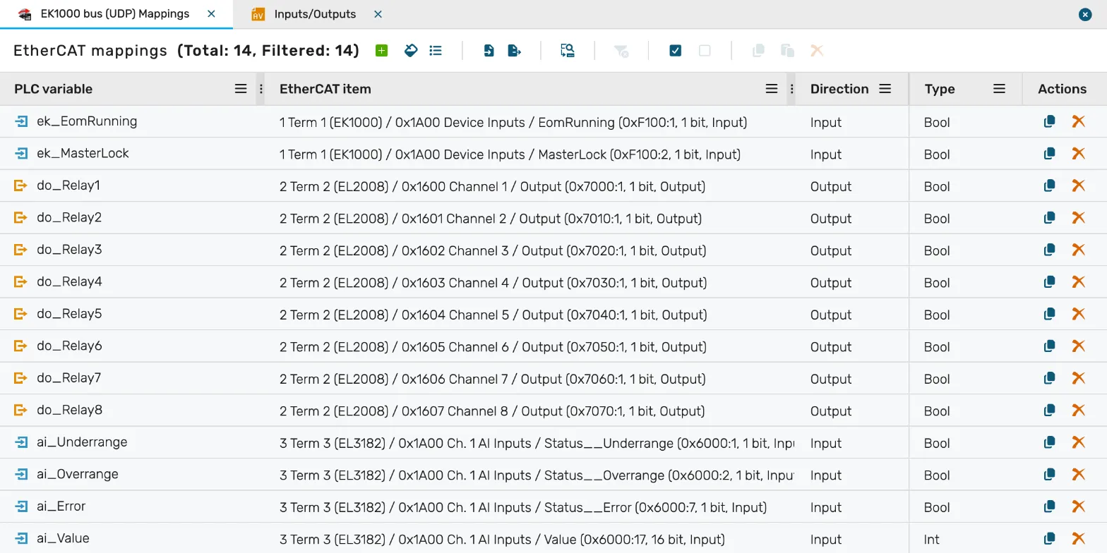
Section titled “5. Map the variables”- Open EK1000 bus (UDP) Mappings.
- Select Advanced fill, tick the 14 variables of the table below, and select Use selected variables. The grid gets one row per variable.
- In each row, select the EtherCAT item. The list shows each entry as
<position> <device> / <PDO> / <entry> (<index>:<subindex>, <bits> bit, <direction>); type part of it, for example0x7000:1, to filter. The Type is preset from the entry.
| PLC variable | EtherCAT item (position, PDO, entry) | Direction | Type |
|---|---|---|---|
ek_EomRunning | 1, 0x1A00 Device Inputs, EomRunning (0xF100:1, 1 bit) | Input | Bool |
ek_MasterLock | 1, 0x1A00 Device Inputs, MasterLock (0xF100:2, 1 bit) | Input | Bool |
do_Relay1 | 2, 0x1600 Channel 1, Output (0x7000:1, 1 bit) | Output | Bool |
do_Relay2 … do_Relay8 | 2, 0x1601 Channel 2 … 0x1607 Channel 8, Output (0x7010:1 … 0x7070:1) | Output | Bool |
ai_Underrange | 3, 0x1A00 Ch. 1 AI Inputs, Status__Underrange (0x6000:1, 1 bit) | Input | Bool |
ai_Overrange | 3, 0x1A00 Ch. 1 AI Inputs, Status__Overrange (0x6000:2, 1 bit) | Input | Bool |
ai_Error | 3, 0x1A00 Ch. 1 AI Inputs, Status__Error (0x6000:7, 1 bit) | Input | Bool |
ai_Value | 3, 0x1A00 Ch. 1 AI Inputs, Value (0x6000:17, 16 bit) | Input | Int |
- Select Save all. Expected:
Successfully saved 'EK1000 bus (UDP) Mappings'. The connection now has 14 mappings.
6. Build, deploy and check
Section titled “6. Build, deploy and check”- Build the project and deploy the runtime to the device.
- Open the log of the EtherCAT connector on the device. Expected lines:
EtherCAT scan finishedwithbus=udp:192.168.2.110:34980andslaves=3EtherCAT master statewithstate=OPandslaves=3
- Switch
hmi_Relay1on in the HMI or the debug view. Expected: the LED of EL2008 channel 1 lights up. - Change the current on EL3182 channel 1. Expected:
ai_Valuechanges.
If the log shows timeout waiting for reply or Topology mismatch, see Troubleshooting.
Variant: layer 2
Section titled “Variant: layer 2”To run the same bus over layer 2, set Open Mode of the EK1000 to RAW, cable it to a network interface of the device, and select Layer 2 (network interface) with that interface on the Bus tab. Steps 2, 4, 5 and 6 stay the same; the log shows bus=layer2:<interface>. On a device installed with the Linux installation script, first install the container with the host network: see Layer 2 on a device installed with the Linux script.